hitz

bidtraffic

cbeckads

Tuesday 29 March 2011

2 km FM Transmitter circuit


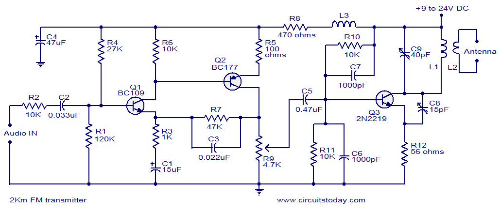
With a matching antenna, the FM transmitter circuit shown here can transmit signals up to a range of 2 kilo meters. The transistor Q1 and Q2 forms a classic high sensitive preamplifier stage. The audio signal to be transmitted is coupled to the base of Q1 through capacitor C2. R1, R3, R4, R6, R5 and R9 are the biasing resistors for the preamplifier stage comprising of Q1 and Q2. Transistor Q3 performs the collective job of oscillator, mixer and final power amplifier.C9 and L1 forms the tank circuit which is essential for creating oscillations. Inductor L2 couples the FM signal to the antenna.
Circuit diagram.
2km Fm transmitter
Notes.
  • Assemble the circuit on a good quality PCB.
  • The circuit can be powered from anything between 9 to 24V DC.
  • Inductor L3 can be a VK220J type RFC.
  • For L1 make 3 turns of 1mm enamelled copper wire on a 10mm diameter plastic former. On the same core make 2 turns of 1 mm enamelled copper wire close to L1 and that will be L2.
  • Frequency can be adjusted by varying C9.
  • R9 can be used to adjust the gain.
  • For optimum performance, value of C8 must be also adjusted.
  • Using a battery for powering the circuit will reduce noise.

Low Cost Fire Alarm Circuit


When there is a fire breakout in the room the temperature increases.This ultra compact and low cost fire alarm senses fire breakout based on this fact.
Transistor BC177 (Q1) is used as the fire sensor here.When the temperature increases the leakage current of this transistor also increases.The circuit is designed so that when there is an increase in the leakage current of Q1 ,transistor Q2 will get biased.As a result when there is a fire breakout the transistor Q2 will be on.The emitter of Q2 (BC 108)is connected to the base of Q3(AC 128).So when Q2 is ON Q3 will be also ON.The transistor Q3 drives the relay which is used to drive the load ie,light,bell,horn etc as an indication of the fire.The diode D1 is used as a free wheeling diode to protect it from back EMF generated when relay is switched.
Circuit diagram with Parts list.
fire-alarrm-circuit.JPG
Notes.
  • The Preset R1 can be used to desired temperature level for setting the alarm ON.
  • This is not a latching alarm,ie;when the temperature in the vicinity of the sensor decreases below the set point the alarm stops.
  • The circuit can be powered using  a 9V battery or a 9V battery eliminator.
  • All capacitors are electrolytic and must be rated at least 10V.
  • The load can be connected through the C,NC,NO points of the relay according to your need.
  • The calibration can be done using a soldering iron,and a thermo meter.Switch ON the power supply.Keep the tip of soldering iron near to the Q1.Same time also keep the thermometer close to it.When the temperature reaches your desired value adjust R1 so that relay gets ON.Done!

Fire Alarm


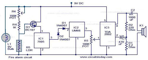
Here is a simple fire alarm circuit based on a LDR and lamp pair for sensing the fire.The alarm works by sensing the smoke produced during fire.The circuit produces an audible alarm when the fire breaks out with smoke.
When there is no smoke the light from the bulb will be directly falling on the LDR.The LDR resistance will be low  and so the voltage across it (below .6V).The transistor will be OFF and nothing happens.When there is sufficient smoke to mask the light from falling on LDR, the LDR resistance increases and so do the voltage across it.Now the transistor will switch to ON.This gives power to the IC1 and it outputs 5V.This powers the tone generator IC UM66 (IC2)  to play a music.This music will be amplified by IC3 (TDA 2002) to drive the speaker.Resistor R6 is meant for protecting the transistor when R4 is turned towards low resistance values .Resistor R2 and R1 forms a feedback network for the TDA2002 and C1 couples the feed back signal from the junction of R1 & R2 to the inverting input of the same IC.
The diode D1 and D2 in combination drops 1.4 V to give the rated voltage (3.5V ) to UM66 .UM 66 cannot withstand more than 4V.
Circuit diagram with Parts list.
fire alarm
Fire alarm circuit
Notes.
  • The speaker can be a 32Ω tweeter.
  • POT R4 can be used to adjust the sensitivity of the alarm.
  • POT R3 can be used for varying the volume of the alarm.
  • Any general purpose NPN transistor(like BC548,BC148,2N222) can be used for Q1.
  • The circuit can be powered from a 9V battery or a 9V DC power supply.
  • Instead of bulb you can use a bright LED with a 1K resistor series to it.

Power supply for the circuit.

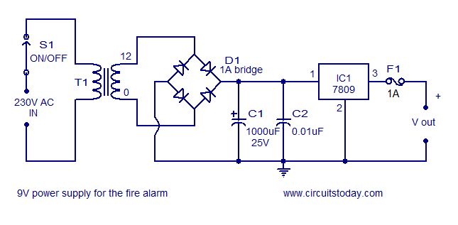
A well regulated power supply is essential for this circuit because even slight variations in the supply voltage could alter the biasing of the transistor used in the fire sensing section and this could seriously affect the circuit’s performance.
9V power supply
9V/500mA power supply circuit
A regulated 9V/500mA power supply that can be used for powering the basic fire alarm circuit and its modified versions is shown above. Transformer T1 is a 230V primary, 12V secondary, 500mA step down transformer. D1 is a 1A bridge which performs the job of rectification. Capacitor C1 filters the rectifier output and C2 is the AC by-pass capacitor. IC1 (7809) is a 9V fixed positive voltage regulator. The output of the rectifier+filter section is connected to the input of 7805 and a regulated steady 9V is obtained at its output. S1 is the ON/OFF switch. F1 is a 500mA safety fuse.

Relay version of the circuit.

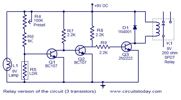
Here the above fire alarm circuit is modified to operate a relay when the fire breaks out. The usage of relay makes the circuit able to switch high power warning devices like alarms, bells,beacon lights etc that operates from the mains.
Relay version of the circuit
Two additional transistors are used with the basic fire sensing circuitry (consisting of Q1, R4, R5 and L1) to attain the target. Whenever the fire breaks out the transistor Q1 is switched ON. The collector voltage of Q1 drops to 0.2V and the transistor Q2 gets switched OFF. This makes the collector voltage of Q2 rise towards 9V and this result in the switching ON of transistor Q3. The relay connected at the collector of Q3 is activated and the load connected through the relay contact is driven. Resistors R7 and R8 limits the collector current of Q1 and Q2 respectively. D1 is a freewheeling diode which protects Q3 from the voltage spikes induced when the relay is switched. Resistor R9 controls the base current of transistor Q3 (2N2222).
Thursday 24 March 2011

String Theory

 Pythagoras could be called the first known string theorist. Pythagoras, an excellent lyre player, figured out the first known string physics -- the harmonic relationship. Pythagoras realized that vibrating Lyre strings of equal tensions but different lengths would produce harmonious notes (i.e. middle C and high C) if the ratio of the lengths of the two strings were a whole number.
   Pythagoras discovered this by looking and listening. Today that information is more precisely encoded into mathematics, namely the wave equation for a string with a tension T and a mass per unit length m. If the string is described in coordinates as in the drawing below, where x is the distance along the string and y is the height of the string, as the string oscillates in time t,

then the equation of motion is the one-dimensional wave equation
Nonrelativistic string equation
where vw is the wave velocity along the string.
   When solving the equations of motion, we need to know the "boundary conditions" of the string. Let's suppose that the string is fixed at each end and has an unstretched length L. The general solution to this equation can be written as a sum of "normal modes", here labeled by the integer n, such that
sum of string normal modes
The condition for a normal mode is that the wavelength be some integral fraction of twice the string length, or
The frequency of the normal mode is then
   The normal modes are what we hear as notes. Notice that the string wave velocity vw increases as the tension of the string is increased, and so the normal frequency of the string increases as well. This is why a guitar string makes a higher note when it is tightened.
   But that's for a nonrelativistic string, one with a wave velocity much smaller than the speed of light. How do we write the equation for a relativistic string?
   According to Einstein's theory, a relativistic equation has to use coordinates that have the proper Lorentz transformation properties. But then we have a problem, because a string oscillates in space and time, and as it oscillates, it sweeps out a two-dimensional surface in spacetime that we call a world sheet (compared with the world line of a particle).
   In the nonrelativistic string, there was a clear difference between the space coordinate along the string, and the time coordinate. But in a relativistic string theory, we wind up having to consider theworld sheet of the string as a two-dimensional spacetime of its own, where the division between space and time depends upon the observer.
   The classical equation can be written as
Relativistic string eqaution
where s and t are coordinates on the string world sheet representing space and time along the string, and the parameter c2is the ratio of the string tension to the string mass per unit length.
   These equations of motion can be derived from Euler-Lagrange equations from an action based on the string world sheet
Bosonic string action
The spacetime coordinates Xm of the string in this picture are also fields Xm in a two-dimension field theory defined on the surface that a string sweeps out as it travels in space. The partial derivatives are with respect to the coordinates s and t on the world sheet and hmn is the two-dimensional metric defined on the string world sheet.
   The general solution to the relativistic string equations of motion looks very similar to the classical nonrelativistic case above. The transverse space coordinates can be expanded in normal modes as
The string solution above is unlike a guitar string in that it isn't tied down at either end and so travels freely through spacetime as it oscillates. The string above is an open string, with ends that are floppy.
   For a closed string, the boundary conditions are periodic, and the resulting oscillating solution looks like two open string oscillations moving in the opposite direction around the string. These two types of closed string modes are called right-moversand left-movers, and this difference will be important later in the supersymmetric heterotic string theory.
   This is classical string. When we add quantum mechanics by making the string momentum and position obey quantum commutation relations, the oscillator mode coefficients have the commutation relations
The quantized string oscillator modes wind up giving representations of the Poincaré group, through which quantum states of mass and spin are classified in a relativistic quantum field theory.
    So this is where the elementary particle arise in string theory. Particles in a string theory are like the harmonic notes played on a string with a fixed tension
String tension
The parameter a' is called the string parameter and the square root of this number represents the approximate distance scale at which string effects should become observable.
   In the generic quantum string theory, there are quantum states with negative norm, also known as ghosts. This happens because of the minus sign in the spacetime metric, which implies that
So there ends up being extra unphysical states in the string spectrum.
   In 26 spacetime dimensions, these extra unphysical states wind up disappearing from the spectrum. Therefore. bosonic string quantum mechanics is only consistent if the dimension of spacetime is 26.
   By looking at the quantum mechanics of the relativistic string normal modes, one can deduce that the quantum modes of the string look just like the particles we see in spacetime, with mass that depends on the spin according to the formula
Regge formula
   Remember that boundary conditions are important for string behavior. Strings can be open, with ends that travel at the speed of light, or closed, with their ends joined in a ring.
   One of the particle states of a closed string has zero mass andtwo units of spin, the same mass and spin as a graviton, the particle that is supposed to be the carrier of the gravitational force.

Questions about Physics


1. Is it necessary that optically denser medium must possess greater mass density? Explain.
Answer:  No. For example,kerosene oil and turpentine oil are lighter than water (as they float on the surface of water) and have less mass density than water. But refractive indices of kerosene oil (nk = 1.44) and turpentine oil (nt = 1.47) are greater than that of water (nw = 1.33)
Q2. Why does sky appear to be blue during daytime to a person on the earth?
Answer: When visible light from the sun passes through the atmosphere, blue colour having smaller wavelength is scattered most. Hence, the sky appears blue.
Q3. Why is a normal eye not able to see clearly the objects placed closer than 25 cm?
Answer: Our eye lens can adjust its focal length due to the action of capillary muscles. This is called power of accommodation of the eye. However, focal length of the eye lens cannot be decreased beyond a certain limit. Therefore,  a person cannot see clearly objects placed closer than 25 cm.
Q4. A person, entering into a dark room or cinema hall, cannot see clearly for a few seconds. Why?
Answer: The iris regulates the amount of light entering into the eye by adjusting size of the pupil of the eye. It takes a few seconds to expand the iris so that proper amount of light can enter into the eye.
Q5. Why are coils of electric toasters and electric irons made of an alloy rather than a pure metal?
Answer: It is because
(i) resistivity of alloys are much higher than those of pure metals which form the alloys
(ii) resistivity of alloys changes less rapidly with change in temperature, and
(iii) they do not oxidize readily at high temperatures.

Q6. Why are copper and aluminium wires usually used for transmission of electricity?

Answer: Copper and aluminium metals have quite low resistivity. It means that resistance of a given copper or aluminium wire of given length and cross-sectional area will be much less and so, there will be very small power losses (I2Rt) during transmission. That is why wires of these metals are usually used for transmission of electricity.

Q7. Why does a compass needle get deflected when brought near a bar magnet?
Answer: A compass needle gets deflected when brought near a bar magnet because a compass needle is a small bar magnet. When two bar magnets are brought close to each other, like poles repel and unlike poles attract each other.
Q8. Why is biogas considered superior to animal dung fuel?
Answer: Biogas is considered superior to animal dung because it has high calorific value and leaves no residue after burning whereas the animal dung has low calorific value and leaves ash after burning.

Q9. Explain why is it difficult to use hydrogen a source of energy.

Answer: This is because hydrogen is highly combustible and it burns with an explosion. Also, hydrogen is difficult to store and transport.
Q10. Tap water conducts electricity whereas distilled water does not. Why ?
Answer: It is because tap water contains some ions of the dissolved salts whereas distilled water does not have any ion.

Hyper Space