Semiconductor Crystals
The Lattice and the Basis
A crystal is a regular, ordered arrangement of atoms over a large scale. The atoms may be of a single type or the repetition of a complex arrangement of many different types of atoms. The crystal can be thought of as consisting of two separate parts: the lattice and the basis. The lattice is an ordered arrangement of points in space, while the basis consists of the simplest arrangement of atoms which is repeated at every point in the lattice to build up the crystal structure. A good analogy, is patterned wallpaper. The basis is like a motif on the wallpaper and the lattice would be periodic pattern of points on which of the motif is repeated. In Figure 1, the lattice points correspond with the centre of the basis, but this does not have to be the case.
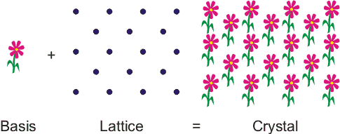
Figure 1. A crystal can be thought of as being like wallpaper. The motif is analogous to the basis and the arrangement of the motif over the surface is like the lattice.
The points on the lattice are specified using vectors. Lattice vectors are the shortest distances to the nearest neighbouring points on the lattice and are conventionally denoted by a , b and c . The angles between these vectors are given the symbols , α, β and γ. A simple two-dimensional example is shown in Figure. 2. Any two lattice points can be reached using a combination of the lattice vectors a and b . Obviously, in three dimensions, any point on the lattice can be reached using a combination of the three lattice vectors a , b and c. In 2-dimensions this is,
The basis vector , R is a vector from one lattice point to another in terms of the lattice vectors. Since the lattice looks the same (invarient) in going from one lattice point to another, the lattice has translational symetry.
Primitive Cell
The primitive cell is the smallest part of the lattice that which repeated would reconstruct the entire crystal structure.
The unit cell - is a volume repeated throughout the entire lattice. The unit cell does not have to be the primative cell.
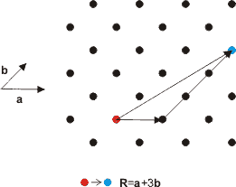
Figure 2. Lattice vectors are a linear combination of the basis vectors.
The Fourteen Bravais Lattices
The ways in which we can specify the lattice points in space and keep translational symmetry is limited. In 1848, Auguste Bravais demonstrated that there are in fact only fourteen possible point lattices and no more. For his efforts, the term Bravais lattice is often used in place of point lattice.
System | Number of Lattices | Lattice Symbol | Restriction on crystal cell angle |
Cubic | 3 | P or sc, I or bcc,F or fcc | a=b=c α =β =γ=90° |
Tetragonal | 2 | P, I | a=b≠c α=β =γ=90° |
Orthorhombic | 4 | P, C, I, F | a≠b≠ c α=β =γ=90° |
Monoclinic | 2 | F, C | a≠b≠ c α=β=90 °≠β |
Triclinic | 1 | P | a≠b≠ c α≠β≠γ |
Trigonal | 1 | R | a=b=c α=β =γ <120° ,≠90° |
Hexagonal | 1 | P | a=b≠c α =β =90° γ=120° |
Table 1. Seven crystal systems make up fourteen Bravais lattice types in three dimensions.
P - Primitive: simple unit cell
F - Face-centred: additional point in the centre of each face
I - Body-centred: additional point in the centre of the cell
C - Centred: additional point in the centre of each end
R - Rhombohedral: Hexagonal class only
F - Face-centred: additional point in the centre of each face
I - Body-centred: additional point in the centre of the cell
C - Centred: additional point in the centre of each end
R - Rhombohedral: Hexagonal class only
Miller Indices and Notation
Miller Indices are used to identify planes of atoms within a crystal structure. Miller indices are written as three digits between brackets, (100) for example. Given the intercepts of the plane with the crystallographic axes. (directions of the lattice vectors), joining the intercepts with lines defines a plane which cuts through the crystal. The Miller indices are calculated by taking the reciprocal of the intercepts and multiplying them by their highest common factor. Negative numbers are represented by placing a bar over the top of the digit. If this sounds at all complicated, it is easily illustrated with a few examples. If the intercept is at infinity, then the plane is parallel to that axis and the Miller index is zero, since, 1/&inf; =0.
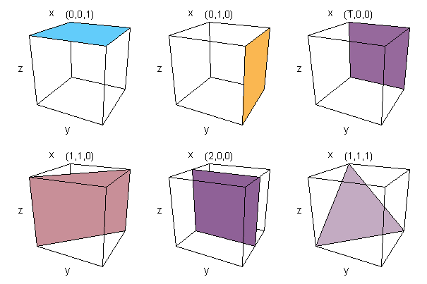
Figure 3. Example Miller indices showing the plane of atoms they represent
The diligent reader may have noticed that due to the symmetry of the unit-cell of the lattice, certain planes are equivalent. In the cubic lattice, for example, (100) is equivalent to five other planes, (010), (001), (100), (010), (001) and to acknowledge this, the set of Miller indices is written {100} which means the set of (100) planes equivalent by virtue of symmetry. The beauty of this system, is that similar planes can be identified in any of the Bravais lattice point groups. The Miller indices are also similar in the way in which planes are described in mathematical terms.
As we saw earlier, a vector from one lattice point to another can be specified in terms of the lattice vectors of the primitive cell. A shorthand notation, directions are often shown as three numbers in square brackets [uvw ] where u ,v , and w are integers and it is important not to confuse these with Miller indices. The direction is then
(1)
Equivalent directions are designated using angled brackets <uvw >.
The Reciprocal Lattice
The reciprocal lattices is the collection of points that represent allowed values of wavevectors for Fourier series and Fourier transforms with the periodicity of the lattice. The value of k allowed for any vector is given by
(2)
where f(k) is the Fourier transform of f(r). The value of k for a second point (also on the lattice) f(r+R) is
(3)
Since the lattice is periodic, we would expect that any 2 points on the real-space lattice would return the same value of k . Therefore, equations (2) and (3) become equal if
(4)
This restriction allows only certain vectors {k }. Vectors that satisfy (4) are given by
(5)
Finally, the vector k is more conventionally given the symbol G.
(6)
Where h,j,l are integers and the vectors a * , b * and c * are the reciprocal lattice vectors. In terms of the lattice vectors a , b , c the reciprocal lattice vectors a * , b * and c * are given by:
(7)
The denominators in (6) are the volume of the unit cell and so act as a normalisation constant. Using the relations for the lattice and the reciprocal lattice the transformation from real lattice to reciprocal lattice can be calculated.
Wigner-Seitz Cell
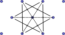
The Wigner-Seitz cell is a primitive cell which displays the full symmetry of the lattice. The Figure below shows the construction of a Wigner-Seitz cell. In reciprocal space, the Wigner-Seitz cell is also a Brillouin zone and we shall use it to construct Brillouin zones later.
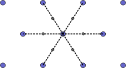 | a) Select a lattice point and draw construction lines to the nearest neighbouring points. |
 | b) Draw lines that perpendicularly bisect the construction lines |
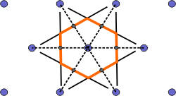 | c) The smallest enclosed area represents the Wigner-Seitz cell. Here shown in orange. |
Figure 4. Construction of the Wigner-Seitz cell.
Brillouin Zones
The Brillouin zone is defined in the reciprocal lattice as the volume enclosed within a Wigner-Seitz cell. At the boundaries of the Brillouin zone, the Bragg diffraction condition in the reciprocal lattice must be satisfied.
(8)
Where k' is the wavevector of the diffracted wave and k is the incident wavevector and G is a reciprocal lattice vector. Squaring (8) gives,
(9)
and assuming the wave is elastically scattered, then k' 2 = k 2 . Equation (9) becomes 2 k × G =- G 2 . Finally, if G is a lattice vector then so is - G and the equation can be rewritten as
(10)
The geometric interpretation of equation (10) is that the diffraction condition is satisfied if k lies in the plane that perpendicularly bisects the lattice vector G .
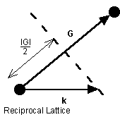
Figure 5. The geometric interpretation of the Bragg diffraction condition that gives rise to Brillouin zone boundaries.
In order to construct the Brillouin zones (BZ), we use the construction method for the Wigner-Seitz cell (WS) outlined above but using the reciprocal lattice space. Further Brillouin zones can be constructed by taking the next nearest set of lattice points from the starting point and repeating the process.
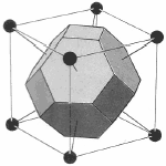
Since the lattice and reciprocal lattice are related, the WS cell defined in real space and the WS in k-space are also related. In particular, the WS defined in the bcc real space lattice gives a fcc BZ in reciprocal lattice and vice versa.
Lattice Real Space | Lattice k-space |
 bcc WS cell | 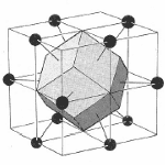 fcc BZ |
 fcc WS cell |  bcc BZ |
Figure 6. The transformation of the WS cell of bcc lattice in real space transforms to a Brillouin zone in a fcc lattice in reciprocal space while the WS cell of a fcc lattice transform to a Brillouin zone of a bcc lattice in reciprocal space.
Points of symmetry on the Brillouin zone are given particular importance especially when determining the bandstructure of the material.
Electrons in the semiconductor are perturbed by the potential of the crystal. The bandstructure of the semiconductor are the allowed energies that the electrons can have. These bands of energy vary with k-space (reciprocal lattice space). Therefore, points of high-symmetry on the Brillouin zone have specific importance. Perhaps the most important, at least for optoelectronic devices, is at k = 0 which is known as the gamma point. As you might expect, it is given the symbol, Γ .
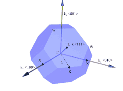
Figure 7. Some important symmetry points on the Brillouin zone of a fcc crystal (real space) and directions of planes. [1]
Symmetry Point | k |
Γ | kx= 0, ky= 0, kz= 0 |
X | {ki= ±2π /a, kj= 0, kk= 0} |
L | {kx= ±π/a, ky= ±π/a, kz= ±π/a} |
Table 2. k-vectors of the important symmetry points for the fcc crystal structure. The indices for X points are a cyclic permutation of axes. E.g. If i=x then j=y, k=z. If i=y then j=z and k=x,etc.
Crystal Structures of Semiconductors
By far the most common crystal structure in semicoductors is the zincblende structure, sometimes known as sphalerite. Closely related to the zincblend structure is the diamond crystal structure. The only difference between the zincblende and diamond structures, is that in the diamond formation there is only one type of atom in the crystal. Real Diamonds also have the diamond crystal structure.
Some semiconductors can have more than one type of crystal structure depending on the conditions in which they are grown. The Nitride semicoductors for example, GaN, InN and AlN can crystalise in either the Wurtzite or Zincblende structures.

Figure 8. Diamonds might be a girl's best friend, but their crystalline structure is closely related to the zincblende structure.
The zincblende structure is described by two interpenetrating face-centred cubic lattices. One type of atom is located on one of the face-centre cubic lattices and the second type of atom is located on another face-centre cubic lattice which is displaced by 1/4( a , a , a ) as can be seen in the 3d model in Figure 8 where the two lattices are coloured orange and blue to distinguish them.
Figure 8. 3D model of Zincblende structure.
The Wurtzite structure can be thought of as two interpenetrating hexagonal close packed lattices.
Figure 9. 3D model of Wurtzite GaN structure.
This example illustrates a complex and important problem that touches on medinical chemistry as well as many others of chemistry (solid state, geochemistry, protein chemistry,...), namely that of determining and characterizing the crystal structures of atoms and molecules. For us, this is a departure from what we have done up to now, which has been mostly focused on single molecules. Crystals are an example of what are generally called condensed phase systems, namely collections of molecules that exist in a particular phase, here, the solid or crystalline phase. Other familiar phases are, of course, the gas and liquid phases. A so-called fourth state of matter exists, the plasma, which can be reached only a very high temperatures.
The fact that some substances can crystallize into several stable forms is a phenomenon known as polymorphism. The most important aspect of a crystal structure is the existence of a pattern or arrangement of atoms or molecules that is then repeated over very long distances. The pattern that is repeated is known as the repeat unit (not to be confused with the unit cell, which we will discuss later). Thus, characterizing the long-range order of the crystal requires characterizing the repeat unit. The latter is accomplished by listing all of the operations that can be performed on the repeat unit, transforming it into a pattern that looks the same as the original one.
The types of operations we can perform are
The first is the identity transformation, i.e. a transformation that does nothing to the cube. This operation is trivial but, nevertheless, it must be included in the set of transformations. Next, there are three axes around which a rotation by 90 transforms the cube into an orientation that looks the same as the original one (see figure).These rotations are known as
  rotations because they are rotations by
  , hence four such rotations bring the cube back to its original state. (In general, a
  rotation is a rotation by
  .) In addition, the figure shows that there are four axes about which a rotation by
  transforms the cube into an orientation that looks the same. These are called
  axes. There are also 6
  axes, 9 mirror planes and finally, one center of inversion symmetry through the center of the cube. This means that if this point were placed at the origin and all of the coordinate vectors of the vertices of the cube in this coordinate system were changed to their negative values, the cube would still look the same.
Example: What are the symmetry operations for the ammonia (NH ) molecule?
First, there is the identity transformation, which leaves the molecule as it was. Then, there is one axis down the center of the pyramid. Finally, there are three mirror planes, each on containing just one of the NH bonds and bisecting the remaining HNH angle.
Shapes of single crystals
The shape of single crystals grown in an artificial environment independent of any other crystals is dictated by the crystallographic structure, with crystal faces in the developing crystallite favouring lattice orientations with the highest density of lattice points. In face centred cubic (fcc) crystals the faces which have the highest density of lattice points are {1,1,1} followed by {1,0,0} where the curly brackets {} signifies the set of faces of that form. Thus {1,1,1} includes the faces (1,1,1), (1,-1,1), (1,-1,-1), (1,1,-1), (-1,1,1), (-1-1,1), (-1,1,-1) and (-1,-1,-1). Crystals with all faces of the form {1,1,1}, (e.g. spinel-group minerals such as magnetite) typically form octahedra. In body centred cubic (bcc) crystals the faces with the highest density of lattice points are {1,1,0} followed by {1,0,0}.

 3.5 Symmetry in crystals

 Centre of symmetryIf every atom in a crystal stucture with coordinates x, y and z is duplicated by an atom at x, y and z, the structure is said to possess a centre of symmetry .
Mirror planes:Planes which divide crystals into mirror ../Images are termed mirror planes.
 Inversion axes of symmetry:
Symmetry operations
In 1996, a particular pharmaceutical company cam put out an anti-HIV drug known as ritonavir (aka norvir). In 1998, the drug was recalled because it was found that its efficacy was not as high as expected from clinical trials. In 2002, the reason became clear. The powered crystal of ritonavir, from which the pills were made, had more than one stable crystal structure, something which was unknown when the drug was first issued. The method of preparation was generating the wrong crystalline form, a form that was less soluble than the one that had been used in trials. The company reissued the drug in liquid form until the crystallization process could be revamped to give the correct form.
This example illustrates a complex and important problem that touches on medinical chemistry as well as many others of chemistry (solid state, geochemistry, protein chemistry,...), namely that of determining and characterizing the crystal structures of atoms and molecules. For us, this is a departure from what we have done up to now, which has been mostly focused on single molecules. Crystals are an example of what are generally called condensed phase systems, namely collections of molecules that exist in a particular phase, here, the solid or crystalline phase. Other familiar phases are, of course, the gas and liquid phases. A so-called fourth state of matter exists, the plasma, which can be reached only a very high temperatures.
The fact that some substances can crystallize into several stable forms is a phenomenon known as polymorphism. The most important aspect of a crystal structure is the existence of a pattern or arrangement of atoms or molecules that is then repeated over very long distances. The pattern that is repeated is known as the repeat unit (not to be confused with the unit cell, which we will discuss later). Thus, characterizing the long-range order of the crystal requires characterizing the repeat unit. The latter is accomplished by listing all of the operations that can be performed on the repeat unit, transforming it into a pattern that looks the same as the original one.
The types of operations we can perform are
- 1.
- Rotations.
- 2.
- Reflections through a plane.
- 3.
- Spatial inversions through a point.
The first is the identity transformation, i.e. a transformation that does nothing to the cube. This operation is trivial but, nevertheless, it must be included in the set of transformations. Next, there are three axes around which a rotation by 90
Example: What are the symmetry operations for the ammonia (NH
First, there is the identity transformation, which leaves the molecule as it was. Then, there is one
3.4 The shape of the unit cell and the crystal systems
Fortunately, there are only seven qualitatively different shapes that a parallelepiped can adopt, and hence the unit cell of all minerals can have only seven qualitatively different shapes. These shapes give rise to seven basic crystal systems characterised by the following properties:
Cubic | a = b = c | a = b = g = 90° |
Hexagonal | a = b ≠ c | a = b = 90°, g = 120° |
Tetragonal | a = b ≠ c | a = b = g = 90° |
Trigonal | a = b = c | a = b = g < 120°, 90° |
Orthorhombic | a ≠ b ≠ c | a = b = g = 90° |
Monoclinic | a ≠ b ≠ c | a = g = 90°, b > 90° |
Triclinic | a ≠ b ≠ c | a ≠ b ≠ g |
Shapes of single crystals
The shape of single crystals grown in an artificial environment independent of any other crystals is dictated by the crystallographic structure, with crystal faces in the developing crystallite favouring lattice orientations with the highest density of lattice points. In face centred cubic (fcc) crystals the faces which have the highest density of lattice points are {1,1,1} followed by {1,0,0} where the curly brackets {} signifies the set of faces of that form. Thus {1,1,1} includes the faces (1,1,1), (1,-1,1), (1,-1,-1), (1,1,-1), (-1,1,1), (-1-1,1), (-1,1,-1) and (-1,-1,-1). Crystals with all faces of the form {1,1,1}, (e.g. spinel-group minerals such as magnetite) typically form octahedra. In body centred cubic (bcc) crystals the faces with the highest density of lattice points are {1,1,0} followed by {1,0,0}.

Schematic illustration of faces with the highest density of lattice points in fcc and bcc crystals, respectively.

Each of the seven crystal systems is characterised by different symmetries. By inspection of the above table we can see that there must be a general decrease in the symmetry from the cubic system down through to the triclinic system. Consequently, the triclinic system is said to have lower symmetry than the cubic system and, conversely, the cubic system higher symmetry than the triclinic system.. In order to understand the basic symmetry elements in crystallography we will initially consider examples of the symmetry elements in a cube (a = b = c, a = b = g = 90° ). The basic symmetry elements are:
Rotation axes of symmetry:
Rotation axes of symmetry are axes which upon rotation reproduce the exact configuration of the crystal. An n-fold rotation axis of symmetry repeats the structure n times in one complete 360° rotation. In crystals rotation axes can be sixfold (termed hexad), fourfold (tetrad), threefold (triad), twofold (diad), or onefold (monad). The monad is a trivial since it merely states that upon rotation through 360° the crystal returns to the initial position. A cube contains a number of different tetrads, triads and diads (try and determine the total number in each case):


Mirror planes:Planes which divide crystals into mirror ../Images are termed mirror planes.

A symmetry type involving a rotation about a line plus an inversion through a point (on the line) is known as an inversion axis of symmetry. In any crystal the operation of an inversion axes of symmetry can always be achieved by a combination of the other symmetry operators in that crystal.
As already stated each of the seven crystal systems have characteristic symmetries. Recognition of these symmetry elements allows us to classify any crystal into the appropriate class. For example the presence of a tetrad indicates either cubic or tetragonal; more than one tetrad and it must be cubic (however, the presence of a tetrad is not the characteristic symmetry element of the cubic system which is, rather, the presence of three triads). Hexads are diagnostic of the hexagonal system, while traids preclude triclinic and monoclinic systems. The triclinic system has no rotational axes of symmetry, except of course the trivial monad. The characteristic symmetry elements in each of the seven groups are listed below:
Cubic | Three triads |
Hexagonal | One hexad (// z) |
Tetragonal | One tetrad (// z) |
Trigonal | One triad (// [111]) |
Orthorhombic | Three perpendicular diads (// x, y and z) |
Monoclinic | One diad (// y) |
Triclinic | - |

